Position : News >> FAQ

Equipment Rack Design Process

2024-04-22
a

In industrial manufacturing, equipment racks are the "backbone" of devices like semiconductor equipment, automated AGVs, and medical instruments. A well-designed rack bears equipment weight, ensures stability, eases maintenance, and adapts to harsh environments. It demands a rigorous design process to balance load capacity, rigidity, and practicality. This article outlines the standard workflow, serving B2B engineering teams, manufacturers, and procurement partners.

1. Requirements Analysis: The Foundation of Targeted Design

Any equipment rack design begins with defining requirements. Close collaboration between the design team, customers, and production departments is needed to confirm key parameters, avoiding rework from vague demands. Core tasks include:
  • Equipment Matching Parameters: Confirm the overall dimensions, weight, and center of gravity of the matched equipment. For example, a semiconductor equipment rack must accommodate the precise layout of internal components, while an AGV rack needs to align with the installation positions of drive systems and battery packs. Additionally, the spacing and accuracy requirements of component mounting surfaces (such as horizontal and vertical tolerances within ±0.1mm for precision equipment) must be clearly defined.

  • Load and Working Condition Definition: Distinguish between static loads (self-weight of equipment and components) and dynamic loads (vibration, impact during operation, or transportation). For instance, racks for stamping equipment must withstand periodic impact loads, while those for laboratory instruments focus more on static stability.

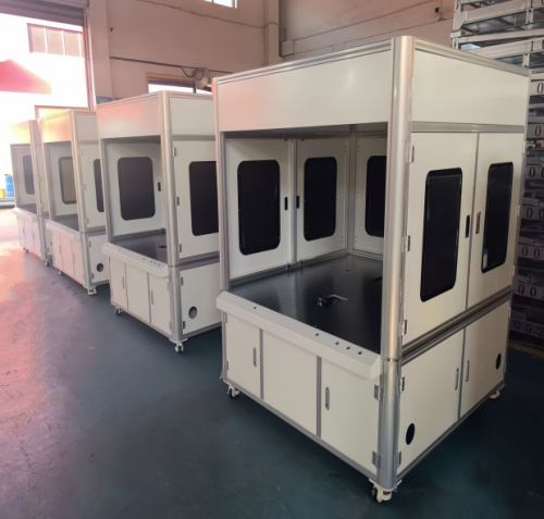
  • Environmental and Compliance Requirements: Clarify the application scenario—whether it is a high-dust workshop, a humid outdoor environment, or a clean room for semiconductors. This determines the need for anti-corrosion (such as galvanized treatment), anti-static (ESD protection), or dust-proof designs. Meanwhile, compliance with international standards such as ISO 10248 (steel structures) or CE (safety certification for European markets) is a prerequisite for market access.

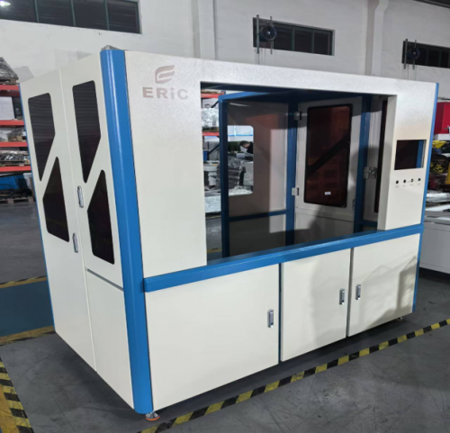
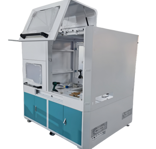
  • Assembly and Maintenance Needs: Reserve sufficient space for component disassembly, cable routing channels, and inspection doors. For example, racks for industrial control cabinets should design removable side panels to facilitate the maintenance of internal electrical components.

2. Load and Working Condition Calculation: Building a Safe Structural Baseline

Load calculation is the "mathematical basis" for structural design, which prevents both over-design (wasting materials and increasing costs) and under-design (posing safety hazards). Engineering teams typically use mechanical calculation tools and empirical formulas to complete the following work:
First, integrate all load types to form a comprehensive load spectrum. For example, the total load of a rack includes the weight of the equipment (500kg), the weight of auxiliary components (100kg), and the dynamic impact load (equivalent to 20% of the static load) during operation, resulting in a total design load of 720kg. Second, simulate extreme working conditions, such as transportation vibration (complying with ISTA 3A standards) or accidental impact, to ensure the rack remains intact. Finally, set a reasonable safety factor—industrial equipment racks usually adopt a safety factor of 1.5-2.0, meaning the rack’s ultimate load-bearing capacity must be 1.5 times or more than the actual maximum load, providing a sufficient safety margin.

3. Structural Scheme Design: Balancing Function and Feasibility

Based on load calculation results, the design team determines the overall structural form and key details of the rack, focusing on "stability, manufacturability, and cost-effectiveness." Common structural design points include:
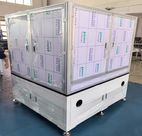
  • Frame Structure Selection: Choose between bolted assembly, welded structure, or a hybrid of both. Bolted racks (using high-strength bolts) are easy to disassemble and transport, suitable for large-scale equipment or overseas delivery; welded racks have higher structural rigidity, ideal for heavy-duty equipment such as forging machines. Profiles such as square tubes (Q235B steel), channel steel, or aluminum extrusions are selected according to load requirements—for example, 80×80×4mm square tubes are commonly used for racks with a load of 500-1000kg.

  • Key Component Design: Columns (the main load-bearing parts) are designed with reinforcing ribs at the bottom and connection points to enhance local rigidity; crossbeams are arranged according to the center of gravity of the equipment to avoid uneven stress; mounting panels adopt punched hole designs (such as M6 threaded holes with a spacing of 50mm) to improve compatibility with different components.

  • Functional Interface Reservation: Pre-design cable management holes (with rubber grommets to prevent cable wear), heat dissipation vents (adapted to the heat output of the equipment), and lifting lugs (for hoisting during installation). For outdoor equipment racks, drainage holes are added to avoid water accumulation and corrosion.

4. 3D Modeling and Interference Checking: Digital Visualization Verification

With the popularization of digital design tools, 3D modeling has become a core link in rack design, replacing traditional 2D drawings to achieve more intuitive and accurate verification. Using software such as SolidWorks, AutoCAD, or Pro/E, the design team completes the following tasks:
First, build a full-scale 3D model of the rack, including all components such as columns, crossbeams, and mounting panels, and accurately mark dimensions and material information. Second, perform virtual assembly with the matched equipment to check for spatial interference—for example, whether the rack’s internal space conflicts with the equipment’s protruding parts, or whether the bolt holes align with the equipment’s mounting points. This step can reduce rework rates in the later production stage by over 30%. Finally, optimize the assemblability: simulate the installation process of components, adjust the position of fasteners, and ensure that workers can complete assembly with common tools.

5. Strength and Stiffness Simulation Analysis: Predicting Structural Performance

To avoid structural failure caused by insufficient strength or excessive deformation, CAE (Computer-Aided Engineering) simulation analysis is essential. Using software such as ANSYS or Abaqus, the design team simulates the stress and deformation of the rack under various working conditions:
  • Strength Analysis: Check whether the maximum stress of the rack (especially at the joints of columns and crossbeams) exceeds the yield strength of the material. For example, Q235B steel has a yield strength of 235MPa; if the simulation shows the maximum stress is 180MPa, the strength meets the requirements.

  • Stiffness Analysis: Control the deformation of the rack within a reasonable range. For precision equipment racks, the maximum vertical deformation of the mounting surface should not exceed 0.2mm/m to avoid affecting the equipment’s operational accuracy.

  • Modal Analysis: Simulate the natural frequency of the rack to avoid resonance with the operating frequency of the equipment. For example, if the equipment’s operating frequency is 10Hz, the rack’s natural frequency should be designed to be higher than 15Hz or lower than 5Hz.

Based on the simulation results, the design is optimized—such as increasing the thickness of the column, adding reinforcing plates, or adjusting the spacing of crossbeams—to ensure the rack’s performance meets the requirements.

6. Detailed Drawing Compilation: The Bridge to Production

After the 3D model and simulation are confirmed, the design team compiles detailed 2D production drawings, which are the direct basis for the production department. The drawings must include:
  • Part drawings: Detailed dimensions, tolerances, material grades, and surface treatment requirements of each component (such as "galvanized after welding, thickness ≥8μm").

  • Assembly drawings: Assembly sequence, bolt tightening torque (such as "M12 bolts tightened to 80N·m"), and key dimension inspection standards (such as "the parallelism of the mounting surface is ≤0.1mm").

  • Bill of materials (BOM): Detailed list of components, including part numbers, specifications, quantities, and suppliers, to facilitate procurement and inventory management.

Drawings must comply with industrial standards such as GB/T 18229 (China) or ASME


Recent browsing: